Kumori: an overlay to reinforce inter-datacenter connections resiliency
 Antoine Fressancourt
- 10 Min To Read
- 19 Jun, 2019
Networking: an essential aspect of cloud computing infrastructures
If you landed on this technical blog, it shouldn’t be a surprise to you if I tell you that cloud computing is the major trend that has shaped the IT world since its appearance in the form of Amazon’s “pay as you go” computing platform offerings. From then on, Cloud computing delivers its users and customers flexibility and adaptability to demand. Cloud services providers also promise a better resilience in the event of a failure, arguing that as their platform exists in datacenters distributed all around the world, their infrastructure can cope with large failures in a better way than a standalone computing rack that companies’ IT departments might run on their premises.
In order to achieve a good resilience while running online services in distributed datacenters, cloud services providers need to interconnect their datacenters using a resilient, failure-proof network; ensuring that data transfers, virtual machine migrations or database replications can be done without any problem or performance degradation. To build such an error-proof network between datacenters, you only have two options: either you build a network that can be repaired very quickly or you build a network that can accommodate failure events by proposing several paths between every node in the network. The first option is unfeasible at a large scale because nobody can repair a network spanning several metropolitan regions efficiently. Thus, most cloud services providers have built a network offering a variety of paths between their datacenters in order to be able to cope with failures. To do so, they have often adopted a design forming a nearly full mesh between their datacenters. This full mesh is most of the time built with a set of private links operating in pairs for the sake of redundancy between the various datacenters of a service provider.
This networking strategy has several inconveniences, especially in the context of multi-cloud applications. First, setting up a mesh of dual private links between datacenters spread around the globe can be a costly strategy. Indeed, this network needs to be used at only half of the deployed capacity for the sake of resilience; and has to be designed to cope with the cloud service provider’s peak traffic. Besides, deploying such links can take quite a long time, which can prevent opportunistic deployments of applications built on top of several cloud services. At last, in such a setup, a cloud service provider will rely either on its contractual agreements or on its own ability to repair failures to repair failing links quickly enough to relieve the stress on the remaining links and avoid putting its network at risk. On the other hand, relying on the Internet’s ability to cope with failures is not an acceptable solution for cloud services providers because the Internet is “only” a best-effort network.
Enter Kumori
This is where the Kumori architecture comes into play. I have had the opportunity to design Kumori while I was doing a PhD in partnership between Télécom Paristech and Worldline. Kumori is what is called an overlay network. Kumori takes its name from the word “Clouds” translated in Japanese. An overlay network is a logical network sitting on top of existing networks that tries to route packet and network flows among its nodes to achieve a set of objectives that is complementary to the design objectives of the underlying networks.
In Kumori’s design, my colleagues and I have tried to enhance the resiliency of the connections between a cloud services provider’s datacenters over the Internet by offering the cloud services provider a method to quickly detect a failure and route its traffic around this failure to avoid it. Kumori aims at rerouting traffic in the event of a failure quicker than the Internet is able to achieve alone.
The Internet uses a routing protocol called Border Gateway Protocol (BGP). It allows network providers to route traffic between their Autonomous Systems (AS), creating the network-of-networks we use today. Due to the characteristics of BGP, it can take up to 5 minutes for a connection between two nodes to recover from a failure in the Internet.
In Kumori, we aimed to drastically reduce this recovery time by allowing Cloud Services Providers to automatically select the route taken by their network traffic on the Internet between their datacenters by using the nodes constituting the Kumori overlay to capture metrics, detect failures and redirect traffic to other Kumori nodes to go around detected failures.
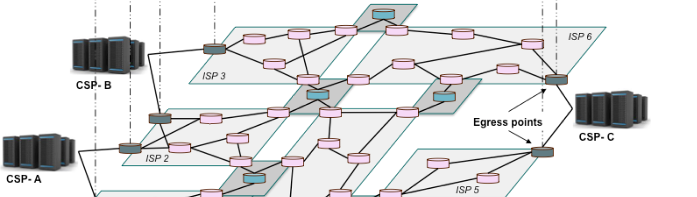
The Kumori architecture consists in three elements: the routing inflection points, the controller and the egress points.
https://blog.worldline.tech//images/post/KumoriArchitecture.png does not existA schematic representation of the Kumori architecture
The controller is the “brain” of the overlay. Its role is to retrieve measurements made by the nodes constituting the overlay and detect performance drifts or failures from an observation of those measurements. If a failure is detected, they are responsible for changing the network routing policy among the overlay by sending routing updates to the Kumori overlay nodes.
The routing inflection points are located in the Internet. They are used to measure the health of connections among the overlay and to apply a set of routing rules they receive from the controller to the various network flows that cross them.
The egress points are the transition points between the datacenter’s network and the Internet. In Kumori, we dedicate an egress point per operator connecting the datacenter to the Internet. For the sake of redundancy, we use at least two network operators connecting the datacenter to the rest of the Internet, thus, we have at least two egress points per datacenter.
When no failure is affecting the communications between the datacenter, Kumori is used to passively monitor current flows between applications or servers residing in the datacenters of the cloud service provider. This surveillance helps in detecting abnormal behavior that can trigger active measurements on the links that seem to be suffering from a failure or a loss in quality. If the active measurements confirm that there is a problem, the controller can trigger the rerouting of the affected traffic among the various elements of the Kumori architecture in order to avoid using the links that suffer from the detected problem.
Evaluating Kumori’s benefits
People familiar with either network resilience or overlay networks might think that Kumori is similar to another overlay network designed to enhance the robustness of connections over the Internet, RON (Resilient Overlay Network) which was presented by Andersen, Balakrishnan and their colleagues in 2001. Yet, RON and Kumori are quite different. First, Kumori uses a central controller to detect failures and provides the routing strategy to the overlay nodes while RON adopts a decentralized model. In RON, the overlay is only composed of nodes located at the border of the network (i.e. the datacenters) while Kumori uses nodes located at Internet eXchange Points (or IXPs). In Kumori’s design, my intention was to locate the routing inflection points at IXPs because IXPs are relatively neutral locations in the Internet and they benefit from a very rich connectivity ecosystem. Yet, this was only a hypothesis during the design phase that needed to be verified. Thus, I spent a long time to verify this hypothesis by comparing the performance of RON and Kumori for two companies / Internet ASs: Atos and Amazon.
Every time you want to compare network architectures or any type of engineering construct, you need to determine two things: which metric is used to measure your performance and which testbed are you going to use.
In order to choose the metric to use, one needs to consider that Kumori’s objective is to enhance the resilience of inter-datacenter connections by providing a method to quickly route network traffic around failures. Thus, Kumori will be more successful than RON or other overlays if it can provide more Internet routes between the various datacenters involved in the overlay. So, we choose the average number of paths available between the datacenters of an organization as the metric to compare RON and Kumori.
To measure the average number of paths between all datacenters of a cloud service provider, we need a representation of the Internet. The Internet is often represented as a graph with various levels in granularity: the autonomous system, the point of presence or the router. Using a router-level graph of the Internet is tedious because this graph is very large and put at the same level long distance connections and links between routers in the same rack. At the other extreme, using an autonomous system-level graph of the Internet is not suitable to measure path diversity because it puts at the same level autonomous systems that span several continents with small, local ASs.
We have chosen to use a directed, point-of-presence representation of the Internet. The direction gives an information of the type of relationship between the various autonomous systems, which is important because it gives information on whether a path can be taken or not. Indeed, some routes between two ASs can’t be taken depending on the nature of their commercial relationship.
At the time of my PhD thesis, there was no PoP-level directed graph representing the Internet, so I built one using publicly available sources. I will write another article to present this building process later, yet if you want some details, you can find a presentation describing how I built this graph here . I then designed a route discovery algorithm to evaluate the number of disjointed paths between two points of presence using this graph.
After building the graph that I used as a testbed for the comparison of RON and Kumori, I performed a set of measurements using two organizations: Atos and Amazon. In this evaluation, I modeled the use of a Kumori overlay consisting in 5 routing inflection points located at large IXPs. The RON overlay consisted in nodes located at every datacenter belonging to the organization. I looked for the disjoint paths among every pair of PoPs for Atos and Amazon using RON and Kumori. I then computed the average number of disjoint paths I could find for both systems. I considered two types of disjoint paths: edge-disjoint paths, which are paths that don’t share any edge, and node-disjoint paths, which are paths that don’t cross the same nodes (except the source and destination).
I compared the measure I obtained to the maximum average diversity, which has been computed by taking the minimum between the number of edges leaving the source and the number of edges arriving at the destination. The results I obtained are shown on the following picture:
https://blog.worldline.tech//images/post/common-average-path-found-per-length-line.png does not existAverage number of disjoint paths found for Atos and Amazon depending on maximum path length
On the left, you can see the results for Atos. For an organization of this size, using Kumori is beneficial compared to RON both in terms of node and edge diversity. The plateau corresponding to the maximum possible diversity is reached more quickly, which means that Kumori allows Atos to use shorter disjoint paths than RON between its datacenters. On the right, you see the results for Amazon. Compared to RON, Kumori enhances the edge-disjoint path diversity for this cloud service provider, allowing it to approach its maximum diversity. Those results can be explained by the difference in terms of connectivity between the two organizations: Amazon has an aggressive peering and edge networking strategy while Atos connects to selected peers and transit providers to connect its datacenters to its customers and their own customers.
Conclusion and references
In conclusion, Kumori has proven to be consistent with its design goals. The path to reach this result has helped my team and I to research topics related to Internet resilience that we are using daily to improve Worldline’s infrastructure. If you want more details on this work, I suggest you to read the following articles:
- An SDN-based network architecture for cloud resiliency which provides a description of the Kumori architecture;
- Kumori: Steering Cloud traffic at IXPs to improve resiliency which describes an evaluation of the Kumori architecture;
- Improved resiliency for inter-datacenter network connections which is the manuscript of my PhD thesis.